|
|
||||
|
|||||
|
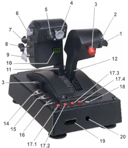
REFERRING TO THE FIGURE CALL-OUTS
1: PDRT Thrust Mode Toggle (ON/OFF)
2: Trailing-edge Flaps
Forward – Deploy
Rearward – Retract
3: Primary Thrust Control Mode Toggle (VMS/MOTO)
4: Target Designation Hat (EXP)
5: Coolie Hat (EXP)
6: Thrust Reverser or Z Velocity Mode
Forward – Deactivates
Rearward – Activates
7: Docking Thrust and Control Modes
Forward – Docking Thrust Mode Toggle
Rearward – Swap SLT and SLR Thrust Control Modes
8: 2-Position Boat (CAUTION: DO NOT USE)
9: 2-Position Arms Select (CAUTION: DO NOT USE)
10: Symmetrical Thrust Control Lock (ENGAGE/DISENGAGE)
11: Inboard Throttle
12: Outboard Throttle
13: Tension Adjust Lever (AKA: Friction Lock)
14: Arms LED
15: Boat LED
16: Turbo LED
17.1: Turbo Selector (WARNING: DO NOT USE)
17.2: Program Button (WARNING: DO NOT USE)
17.3: Erase Button (WARNING: DO NOT USE)
17.4: Internal/External Selector (WARNING: DO NOT USE)
18: Rudder Selector (WARNING: DO NOT USE)
19: Input for External Analog Interface (CAUTION:
AUTHORIZED MAINTANENCE USE ONLY)
20: Input for External Keyboard Interface (CAUTION:
AUTHORIZED MAINTANENCE USE ONLY)
ABBREVIATIONS
EXP Expansion, not currently supported in software
SLT Captain’s station controls the translational thrust and therefore the co-pilot’s station controls the rotation
SLR Captain’s station controls the rotational thrust and therefore the co-pilot’s station controls the translation
PDRT Plasma Drive Ring Turbine is a thrust mode that uses a portion of the plasma thrust to drive air-breathing turbofans for better efficiency in the lower atmosphere
LED Light Emitting Diode is a form of illuminated indicator
OPERATION PRINCIPLES
The throttle is located as the power quadrant on the pedestal between the two crewmember stations. This throttle system is used for operating the four (4) primary or main propulsion engines by wire.
For ease of use in space flight, rather than manipulating the output thrust of the engines as with conventional aircraft, this vessel incorporates a “velocity seeking” (VMS) system. The desired velocity is selected exponentially from 0 km/s to 10 km/s in normal mode and 0 km/s to 1 km/s in docking mode (7). The computer then fires thrust in the most efficacious manner to reach this desired velocity.
OPERATION PRINCIPLES (Continued)
Similarly, the Thrust Reverser (6) selects the desired velocity as a positive or negative value and the computer determines whether forward or reverse thrust actually needs to be fired.
Furthermore, if turning the vessel or encountering gravitational pulls or friction as a result of atmospheric entry alters the forward velocity vector, the computer will strive to maintain the selected velocity automatically.
The conventional direct modification of thrust output (MOTO) can be selected by mode through the Primary Thrust Control Mode Toggle (3). Since the velocity can easily get out of hand in the relative absence of resistance in space, this is recommended only for use in the atmosphere. It is arguably easier to continue to use the VMS system in the atmosphere, as the transitions are easier between atmosphere and orbit and vice-versa. In this mode, the Thrust Reverser (6) acts as a true manual activator of the thrust redirection.
PDRT Thrust (1) is more efficient below 38 km; therefore the checklist calls for its use only in that range.
Normally the Symmetrical Thrust Control Lock (10) is left in the locked position except in an engine failure emergency. CAUTION: This controls inboard and outboard engine pairs, NOT port and starboard engine sets
There is a detent in the stroke of the throttle control, which is more evident when the Friction Lock (13) is set high. Just past this detent to the bottom of the stroke is a 0 km/s requested speed. It is most useful NOT to pull the control past the detent unless the vessel will be at station keeping when the crews’ attention is diverted from operation of the vessel. It is also easier to operate the throttle for fine thrust controls (such as in docking) if operations are kept above the detent.
There is an upper detent, which automatically selects 100 km/s in normal mode or 10 km/s in docking mode (7).
The Primary Thrust Control Toggle (3) simply selects whether or not the computer should be attempting to match the control input. This is useful when selection of a desired speed it to be laid in without immediate reaction of the computer. For this reason, this toggle must be operated when the vessel is first powered up in order to deactivate this incorporated safety feature.
The use of SLT and SLR thrust modes (7) is outlined in the “Flight Controls” system description. The effects of the PDRT Thrust (1) on these flight controls and the flaps are also covered in that section.

Leave a Reply