A successful test flight was completed today. Jason Reskin and Ian Lambert remained in the cockpit for the entire mission. The largest problem to deal with was the asymmetrical thrust compensation. There was a computational error made by our team which resulted in an effective compensation 1/1000000th of the necessary value. Additionally, the atmosphere effects are still offline, as is tactical. After seeing Starship Troopers finally, it was decided that the viewscreens could use a lot of work to simulate the apperances of our universe, but speed has always been an issue. Ian worked on some texture maps that may help liven things up, but we probably need some programmer from one of the big game companies on our side. We will continue to work with what we know, and if anyone has any suggestions, they would be welcomed!
Blog
-
Tuesday, August 18, 1998
A successful test flight was completed today. Jason Reskin and Ian Lambert alternated between dockmaster and flight officer positions leaving Cadet Amy Riley at the controls to learn. We reverted to an older code for handling the primary thrust control inputs. Up until this point, the newer code made space travel easier in that the throttle controlled a desired speed variable, and let the primary computer core handle the required accelleration and decelleration curves. As everyone becomes more comfortable with the complexity of the flight, and as new innovations are made making the information displays more helpful, we can revert to the more realistic yet harder control method of actually controlling exponential thrust from 0 to 20 meters/second². This is not without its intertial disadvantages, which will need to be addressed in the upcoming test flights. Other side effects left Cadet Amy Riley to learn without the advantages of asymmetrical thrust compensation, something everyone should try at least once in their life.
-
Atmospheric Brightness
Atmospheric Brightness
Several principles combine to make this calculation one of the most complicated thus far. As seen in the diagram below, three distances are available with the vertices provided at any given position, X, Y, and Z.
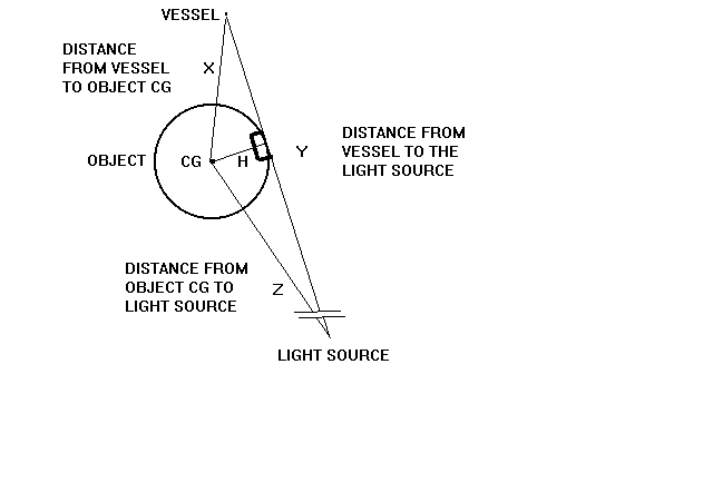
It is known from vector math that if you take the two normalized directional vectors and cross-multiply them by each other, you get the cosine of the angle between them and can therefore determine the angle itself…
temp1 = 1 / sqrt(Zx² + Zy² + Zz²)
Zx = Zx · temp1 Zy = Zy · temp1 Zz = Zz · temp1
temp2 = 1 / sqrt(Yx² + Yy² + Yz²)
Yx = Yx · temp2 Yy = Yy · temp2 Yz = Yz · temp2
temp3 = sqrt(Zx · Yx + Zy · Yy + Zz · Yz) angle = cos-1 (temp3)
To determine the value for H, you multiply the sin of the angle by the length of the hypotenuse of the triangle we are determining the angle within (Z).
H = Z · sin (angle)
All that is left in determining a brightness factor is comparing this H value with the radius of the object in question. We perform this by dividing H by the radius (2573km for PIII M2). This will give us a value of 1 when the light source is exactly perpendicular to our perspective with respect to the object, and an increasing amount into infinity as the vessel travels away from the planet. Since a factor from 0 to 1 for brightness would be more helpful, we simply subtract 1. This value must be magnified so that the full effect of sunlight is available when H is 1km above the surface. The value must then be clipped so that the upper and lower bounds are 0 and 1 respectively.
factor = H/2573/1000000L factor = factor-1 factor = factor * 2573
if (factor > 1) factor = 1 else if (factor < 0) factor = 0
Finally, this value is multiplied by the reference vessel’s altitude (distance to CG minus radius) over the altitude where visual effect of the atmosphere is negligible (48 kilometers for PIII M2) to simulate density decrease exponentially with higher altitudes.
factor = factor · sqrt(altitude) / sqrt(48)
A remarkable transformation of a single RGB combination of the VGA palette is performed as the vessel climbs from the surface of a planetoid on into space. The stars must seamlessly blend into the brightness of the blue sky of day on the surface, and yet maintain their full luster at night from the ground or on into the vacuum of space. The upper and lower ranges for each of the RGB colors from ground to sky are as follows…
On ground: RU = 0 GU = 0 BU = atmopallettefactor / 64
RL = 0 GL = 0 BL = atmopallettefactor / 64
In space: RU = 1 GU = 1 BU = 1
RL = 0 GL = 0 BL = 0
Since each of the window simulator screens has different properties due to variations in construction, brand, and settings of both the monitor and video card, up to 5 different atmopallettefactor’s exist. We will choose one for the purpose of these computational examples…
atmopallettefactor example would be (45 – factor · 45)
We can see that neither RL or GL change during the transformation, so they are left at the constant of 0. However, RU and GU linearly increase from 0 to 1 during the transformation, just the same as the factor previously discussed. Therefore…
RU = factor GU = factor
Since the difference between the two BU’s is ((64 / 64) – (atmopallettefactor / 64)), we simply multiply this difference by the factor as well. An example of this value is shown below based on our (45 – factor · 45) atmopallettefactor example…
BU = (64 – 45) / 64 · factor + (45 / 64)
Likewise, the difference between the two BL’s is ((0 / 64) – (atmopallettefactor / 64)), and using the same example…
BL = (45 / 64) – ((45 / 64) · factor)
Another idea pending is to only update the factor from station_R if (factor · 63)’s integer result is different than before since there are only 64 shades available for each color.
To add the final touch, a starlight twinkle effect is added to the statstar routine which will only be evident when in the atmosphere and when the stars can be discerned from the blue sky. This takes very little extra CPU time since A) the twinkle variable is global and doesn’t have to be passed to the statstar routine each time, B) the twinkle variable is of type int, and C) the color change is only applied to the few stars that pass all other display tests (only the ones that are possibly visible). The twinkle variable is set to 32766 to indicate no twinkle effect when factor equals 1.2, a signal to the view program that the viewpoint is in clear space (not in atmosphere). Any other time, the twinkle effect level is randomly set to a value between 1 and 99 since there is no altitude information available to the view system.
It should be noted that one of two previous attempts to create the atmospheric factor value resulted in a revelation about the inverse tangent function in trigonometry. Take the number of radiuses you are away from a perfect sphere’s surface, subtract one, and then taking 90 minus the inverse tangent of that value gives you the angle that you can see around the planet. For example, on the surface (1 radius) the result is 0°, at 2 radiuses, the result is 45°, and at 3 radiuses that value is ~26°. This may be useful for something in the future, such as keeping from having to rotate the entire universe around the viewer rather than specifying a viewcone.
-
Terminal Approach and Departure Procedures

There are basically two (2) navigational components used to successfully approach and depart a docking area. They are comprised of a navigational marker that is designated by the station name and the port letter from the Greek alphabet (ie. Century City (I) would be Century City’s Iota docking port) which lies in line with the actual docking port it represents at a distance of two (2) kilometers. The docking port itself emits a beacon that can be used for final alignment and distance information when docking (selectable on EFIS as a docking port and not a navigational object, the opposite of the marker). Additionally, there is a virtual marker one (1) kilometer out from the docking port directly in between the two (2) kilometer marker and the docking port itself. This is identified by the distance alone and is not selectable by EFIS. This virtual marker is used for departing traffic only unless notified to report it on approach by the dockmaster.
On approach, the navigational object selected should be the CG of the station (unless only one docking port is available for use). It is recommended that any operations within 10 kilometer of the station be performed with collision avoidance in mind, and voluntary use of running and navigational lighting helps. Outside the 5 kilometer veil, clearance must be attained and at that time the navigational marker for the docking port can be selected if it has not already been. Alignment and thrust inbound is then achieved and clamping to the port can be performed.
On departure, clearance must be received before detaching from the port. Asymmetrical regulation should be deactivated for a smooth transition to the virtual marker using either the 2 kilometer marker or the docking port beacon itself as a reference. At that point, vessels are allowed to turn to their on-course heading (unless otherwise specified). In addition to using normal collision avoidance procedures, it is advised to follow the departure cones so that the outbound course does not backtrack over or too close to the inbound approach path and so the dock and other ports (if applicable and vessels that may be attached to them) are cleared.
-
Turbulence
Overview of Turbulence Graph on EFIS
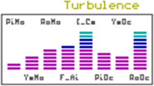
In order from left to right…
Code Description
_____ _______________________________________________________________________
PiMo Currently experienced pitch oscillation is causing this longitudinal axis modification
YaMo Currently experienced yaw oscillation is causing this directional axis modification
RoMo Currently experienced roll oscillation is causing this lateral axis modification
F_Ai Air turbulence factor currently being experienced by the vessel’s aggregate accelerometer input
I_Ce Estimated turbulence that should be expected at current level based on meteorological data
PiOc Currently experienced pitch oscillation varies with air density and wind shear intensity
YaOc Currently experienced yaw oscillation varies with air density and wind shear intensity
RoOc Currently experienced roll oscillation varies with air density and wind shear intensity
Typically, the thicker the cloud layer, the more intense updraft and downdraft activity will be experienced. The computer then bases its estimate of the expected air turbulence (I_Ce) based on the current cell activity (I stands for Intensity and Ce stands for Cell). These thicker cloud layers forming cells show up on the meteorological information available on the EFIS. One should not expect to experience the full effect of the expected I_Ce in all situations. Some cells may be building intensity and others may be diminishing and there is no display representing that stage change. One should, however, never experience turbulence greater than the estimated I_Ce (F_Ai should never exceed I_Ce in normal conditions) otherwise an error should be reported with the EFIS.
The nature of wind shear is that it most greatly affects the longitudinal and lateral axis. The directional axis experiences an average of 33% that of the other two axis. This is due to a predominantly vertical exchange of air due to uneven heating of the planetoid. This may be uneven between the port and starboard sides of the vessel causing a lateral oscillation, or more commonly during forward movement a differential between the bow and stern of the vessel causing longitudinal oscillations. The longitudinal commonality does not increase the intensity of the oscillations but increases the structural strain exponentially as the vessel increases velocity through rough weather.
Verbal notifications only include a hull ionization report which is usually experienced in larger storms (I_Ce of more than 75%) due to the exchange of electrical charges between the clouds and the vessel. Lightning strikes on the vessel are rare but can happen. During flight through violent storms, non-extensionary shielding should be raised as a effort to discourage the ionization from forming.
-
Real TV 2
From: Jason Reskin – reskin@pol.net (Internet E-mail)
To: Allyson Barth – Real TV
1040 Las Palmas Avenue
Stage 2
Los Angeles, Ca 90038
213-860-5134
January 11, 1998
Ms. Barth,
This is in response to your letter received via electronic mail on December 15, 1997. We are glad you are interested in the footage of our ATL (all-terrain lander) space simulator that was designed and built by myself and my friends, and is currently housed in my basement. Enclosed is video of a flight from start to finish with myself and Ian Lambert at the controls (Ian Lambert is in the left seat, the active captain’s position) that was recorded on January 3, 1998, footage from a video with a guest star during a very turbulent landing and takeoff, interview with the individuals of the team, and some shots of construction of this model, and a clip of flight video from the previous simulator.
I apologize for taking so long to get this out to you, but with the holidays and all the time has just flown by.
The tape proceeds in the following order:
July 12, 1997: Ian and Jason are assembled for introduction (Chip has the camera) and then an inside tour of the simulator in a powered down state is conducted. Then back outside to show complex wiring and the sign showing the simulator’s christened name, Audrey. Next, some old footage of the construction is shown when a mini-lab was set up just outside the ship to do programming.
Then we go upstairs to show the dockmaster’s station where other vessels are controlled from during the simulation. This does not require a human, but the logic is more realistic when an extra hand is available.
August 3, 1997: Ian and Jason are doing a test flight when a component of the TC controller blew out.
To show that ready access is important, the panel is removed and the component is replaced
with little delay as would be required in a real vessel’s avionics bay.
January 3, 1998: Ian and Jason on another test flight, undocking procedure and orbital insertion. This is
interrupted but returned to later to complete the rest of the tape because of…
December 28, 1997: Ian and Joanna; a much more impressive planetfall ending in a crash landing and
then a takeoff after simulated repairs are made, both during simulated turbulence.
July 12, 1996: Footage from one of the previous (much larger) simulators with a full crew of 6 people,
Phillip, Bryan, Ian, Jason, Wade, and Robert conducting cartography and rendevous with a
Unistellar port in the Betelguese system.
The tape ends with the rest of the flight from January 3, 1998 including the shutdown sequence which I
thought may work well with your credits at the end of the program like you do.
Here are the facts, as requested:
The simulator is the 8th in a series of simulators we have made over the last 10 years. This one is the second smallest, and the only one that is completely self-contained (all of the components are enclosed within the framing so it can be moved, lifted, or even shook around on a 6-axis platform like the professional flight simulators use.
The simulator weighs almost 2000 pounds (a ton) and rests on 5 shock/strut assemblies taken right out of cars at a salvage yard. It is powered by eleven Intel 80486 computers on a 10 mega-bit network.
The simulator runs on 3 kilowatts of electricity an hour (about as much as 2 or 3 hairdryers) and has its
cell power supply, environmental systems (heating, air-conditioning, air-filtration, and ventilation) as well as lighting and supply boxes for rations (especially nice on long missions).
The simulator is housed in my parent’s house, where I still live while attending college. Our house is in Kansas City on the Missouri side about 5 minutes south of Kansas City International Airport under the runway 1L glide path. The exact address is listed at the top of this document.
The simulator can be flown by one occupant, but the workload is cut into a third if one additional person is available. A jump seat is available for a observer inside the cockpit itself. We also have a position for a dockmaster (kind of like an air traffic controller) when there are enough hands available.
Involved since the beginning are…
Jason Reskin, age 22, currently attending Central Missouri State University in Warrensburg, Missouri as an Aviation and Flight Operations major in my 1st year. I currently hold an FAA private pilot certificate and, by the time you receive this, I should have my instrument rating added to that. I also have 4 years of programming and network experience with a company I owned between the ages of 17 and 21 that was a licensed Missouri corporation called Tyrell Corporation which is also the name of the company from the movie Blade Runner (1982, Harrison Ford).
My role is 90% of the programming, 100% of the hardware/software purchase and maintenance,
90% of the construction, and 100% of the cost involved (well over $40,000 including the other 7
ships that have been made), 75% of the design on this model, and since it is in my house, I am available for 100% of the flights we take.
Ian Lambert, age 21, currently attending Kansas State University in Manhattan, Kansas as an architectural major in his 5th year. He really doesn’t want to be an architect, he would rather make movies for a living when he is out of school. He has realized a lot of potential with set building as a result of his involvement. He also has an active imagination and helps give purpose to some of our flights by developing adventures and creating other ships and docks that we can interact with.
His role is 10% of the construction and 25% of the design of this particular model, 5% of the programming, and is available about 50% of the time, or whenever his girlfriend isn’t.
Wade Tripp, age 23, a graduate of the University of Missouri in Kansas City as a computer science major with an emphasis in software engineering. He works part-time at a local library and full-time at Park College in their CIS department. Wade is somewhat difficult to impress. He reads a lot and has the largest collection of books that I know of aside from the library he works for. He enjoys science fiction films and programming.
His role is 5% of the programming and is available about 50% of the time.
There are others that have had involvement at one point in their lives with our project, but had to move on with education, family, and employment. This may happen to everyone someday, but for now we are just having great fun. Included in that list is Philip LaFollette, Bryan Ball, Aric Wilkerson, Jonathan Lewis, Jeff Epperly, Casie Harmen, Amy Riley, Jenny Locks, Chip Fay, Joanna Keele, Robert Grabowski, and Rachael Grabowski.
We have 30 tapes each from different missions that we went on, all of them are hours long. I tried to send you as much recent and interesting footage as I think you could use. If there is any particular mission you would like to have the entire flight video for, I can copy it in an instant.
If there is anything else I can provide, explain, or do, please let me know! My home number (weekends) is (redacted) and my home number (at school) is 816-543-0183.
Jason Reskin
-
Debugging Example
Problem: Roll rotation fires intermittant bursts rather than one continuous
jet. As a side effect, the asymmetrical thrust compensator, when
active, renders it useless because the computer beleives the pilot
is not firing continuously and therefore fires opposite thrust to
end the rotation.Solution: Maintanence concluded after several test changes to thrust control
computer that the issue was not software related. Maintanence then
proceeded to replace the firing control when a selector that is
publicized for use in the ship’s manual was in the AUTO-FIRE
position which is only used in older model control computers that
did not support the asymmetrical thrust compensator.Result: Tested and returned to normal service on December 25, 1997, 10:07am.
-
Science, a Place for God
The following is my stated theory to define creation.
The universe consists of an infinite amount of space. Any area of space,
large or small, can only be defined by using other points of reference and units of measurement. For this reason, there is no boundary set on our universe. An infinite vacuum must have always existed, much the same as all real numbers from negative infinity to positive infinity exist in mathematics. Any one number can be easily defined, but by itself is of little value in defining an area of space.Time is not linear. It has been proven that time is constant from any given viewpoint, but from external viewpoints it varies on the speed in which the given viewpoint is traveling. An example would be to place yourself in a hypothetical space vessel. If you flew by our solar system close to light speed, time within your space vessel would continue normally. If you ran around in front of the windows, however, and assuming that someone on Earth could see your ship (since there is some question as to whether optical effects would be caused by a vessel travelling at almost the speed of light) they would see you standing completely still. Another problem is that time around you would advance at an incredible rate. For every second that goes by during life
on your ship, hundreds of years may pass on Earth. For this reason, relative time travel is possible, but only forward, never backwards. We also know that at absolute zero (0°K) matter at at least the molecular level comes to a standstill. And if matter can not move, no time
will progress for the matter.It is known that matter can be created from pure energy and that pure energy can be released from matter. Albert Einstein’s equation, e=mc² shows that the amount of energy required or released in a matter/energy conversion is enormous and directly proportionate to the speed of light to the power of 2 (or at least 2 as some scholars may argue). For all matter that exists, there must be, elsewhere in the universe, an equal amount of anti-matter. The definition accepted for anti-matter is identical to that of known matter with one exception. When a quantity of matter is presented to its anti-matter counterpart, the reaction, which can not be replicated by mankind, is a complete, total, and instant conversion to pure energy. For this reason, anti-matter (assuming it exists) can not be anywhere in the vicinity of matter, otherwise neither would exist in their respective states. At one time, however, the energy that matter and anti-matter are comprised of must have come from the same source.
An explosion, like the Big Bang theory, would have had enough
energy of its own to instantly separate the matter and anti-matter and
discharge them off in opposing directions from one another. In theory, when you look up at the night sky, half of the galaxies you see could be comprised of completely matter and the other half would be completely anti-matter. This may not be the case, however. The galaxies that consist of anti-matter may even be beyond the range of even our most powerful telescopes.Science’s place for God exists in the pure energy that created our known
universe. For this reason, the Bible is subjectively correct in many ways.
One would be that God is all around us. Since the matter and energy all around us is a product of that original Big Bang, this would seem correct. Also, since we are made of the same matter and energy as created the rest of the universe, the fact that we were created in God’s image also holds true. And if someone were around back then, the creation of Earth and the first man in a figurative sense over a matter of a week or so is pretty close to what one would have seen during Genesis, although it may have taken much longer to take shape.